Table of Contents
Dielectric Constant Measurement Using Microstrip Ring Resonator Method
Overview
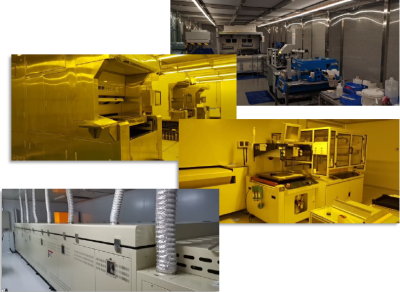 My friend's company has capability to manufacture high precision circuit based on photolithography process. At current process node, the minimum trace width is 5um and the substrates can be either HTCC (High Temperature Co-fired Ceramic) or LTCC (Low Temperature Co-fired Ceramic). We are digging in the possible RF applications for current process node. Thus, the dielectric constant is one of the important characteristics which has to be measured.
There are serval methods for dielectric constant measurement. A very specific test method which may or may not correlate to the microwave application of interest. The Dielectric Constant which is reported for a material can be dramatically different by the test methods. [1] In this article, a HTCC substrate is measured by using the Ring Resonator method.
The Ring Resonator method has following advantages [2]:
- A closed ring with no gaps eliminates much of the fringe effect.
- Resonator rings ensure minimal or negligible loss by radiation, so that Er can be calculated more accurately.
- The results refer to very narrow band ranges/widths (resonance); this avoids issues connected to spurious modes.
The Ring Resonator Design
 The substrate thickness is 0.5mm and silver conductor thickness is 5um. HTCC substrate was manufactured by using Al2O3 thus the Er could be expected to be about 9.8.
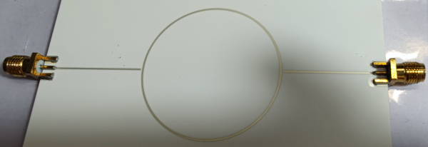
According to above data, the width of 50 Ohm microstrip line is 0.48mm. Finally, the resonator ring could be designed with a 20mm radius ring, 0.4mm gap and 0.48mm microstrip line width.
The ring will resonate at multiples of lambda which corresponding to the circumference of the ring.
When Er = 1, the resonate frequency points can be calculated by following equation:

Thus,
| N | Fo(n) |
|---|---|
| n=1 | Fo(1)=2.386882627 GHz |
| n=2 | Fo(2)=4.773765255 GHz |
| n=3 | Fo(3)=7.160647882 GHz |
| n=4 | Fo(4)=9.54753051 GHz |
| n=5 | Fo(5)=11.93441314 GHz |
| n=6 | Fo(6)=14.32129576 GHz |
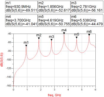
When Er = 9.8, the simulated resonate frequency points:
Measurement
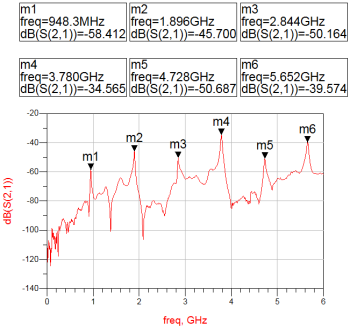
 Six peaks of S21 were measured within the frequency from 300KHz to 6GHz:
 Thus for Fn with n=1…6,
| N | Fn |
|---|---|
| 1 | F1 = 0.9483 GHz |
| 2 | F2 = 1.896 GHz |
| 3 | F3 = 2.844 GHz |
| 4 | F4 = 3.78 GHz |
| 5 | F5 = 4.728 GHz |
| 6 | F6 = 5.652 GHz |
The effective dielectric constant is defined as
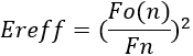 And due to (W/H) <1, so that the dielectric constant is defined as
 H is substrate thickness, 0.5mm for this DUT
W is the width of microstrip line, 0.48mm for this DUT
Finally, the effective dielectric constant and dielectric constant can be calculated by using above two equations:
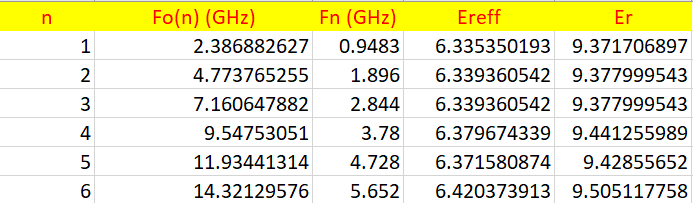 We could conclude that this substrate has stable dielectric constant (Er) over wide frequency range. The average dielectric constant within the frequency from 1GHz to 6GHz is 9.42.
Reference
[1] Neil Hao. The Considerations of Antenna Design for IOT and Wearable Devices. Retrieved Oct 21, 2021, from https://uniteng.com/index.php/2019/11/20/the-considerations-of-antenna-design-for-iot-and-wearable-devices/
[2] Measuring the dielectric constant 𝜺𝒓 of Teflon, Polyester, FR4, G10, or FR4 with an RF generator and a good bolometer. Retrieved Oct 21, 2021, from https://www.e-doodles.it/wp-content/uploads/2019/05/Measuring-the-dielectric-constant-%CE%B5_r-of-Teflon-Polyester-FR4-G10-or-FR4-with-an-RF-generator-and-a-good-bolometer.pdf