Part I: Introduction
I designed two preamplifiers which can be added to any application needs additional gain. The two designs have the same PCB layout but different IC U1 which is shown in the Figure 1. The PCB is shown in the Figure 2.
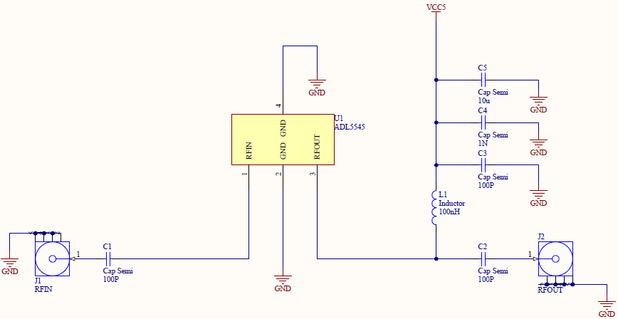
Figure 1: Schematic of the Preamplifier (ADL5544 for fixed gain of 17.4 dB, ADL5545 for fixed gain of 24.1 dB, Full Schematic)
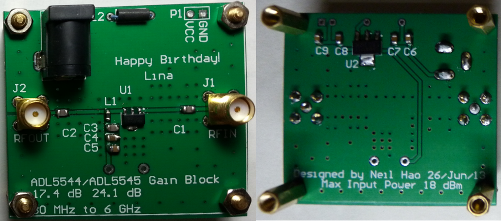
Figure 2: PCB of the Preamplifier
Common Features:
- Broadband operation from 30 MHz to 6 GHz
- Noise figure of 2.9 dB at 900 MHz
- Max Input Power 18 dBm
- Input/output internally matched to 50 Ω
- Single 5V power supply
- Wide operating temperature range of -40°C to +105°C
- ESD rating of ±1.5 kV (Class 1C)
Unique Features for the Preamplifier with ADL5544:
- Fixed gain of 17.4 dB
- Low quiescent current of 55 mA
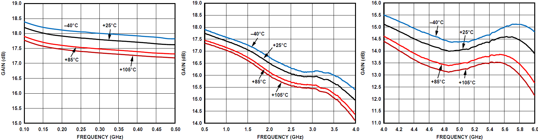
Figure 3: Gain vs. Frequency and Temperature (Click to enlarge)
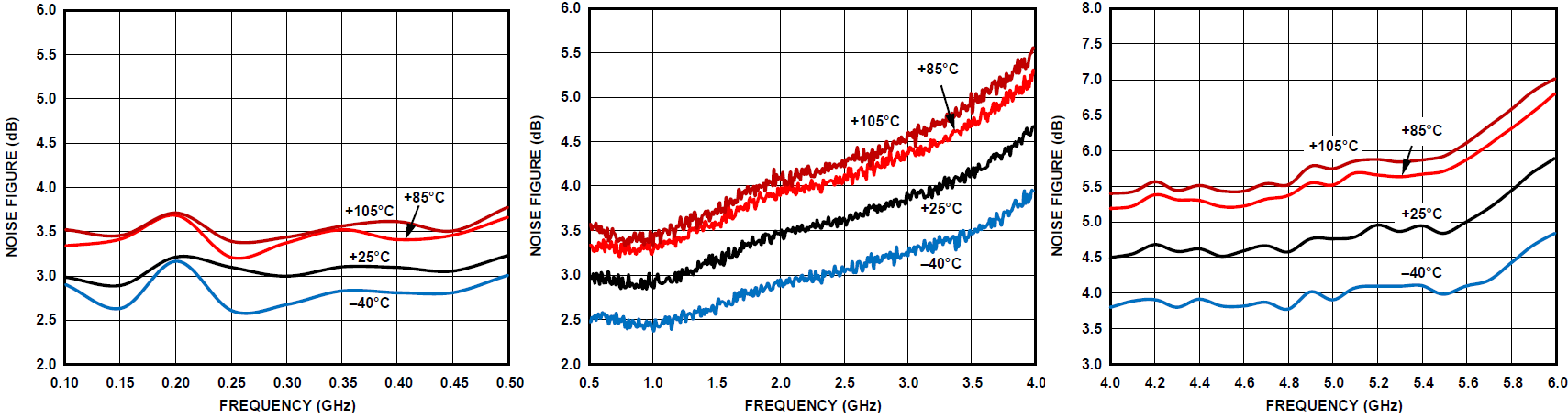
Figure 4: Noise Figure vs. Frequency and Temperature (Click to enlarge)
Unique Features for the Preamplifier with ADL5545:
- Fixed gain of 24.1 dB
- Low quiescent current of 56 mA
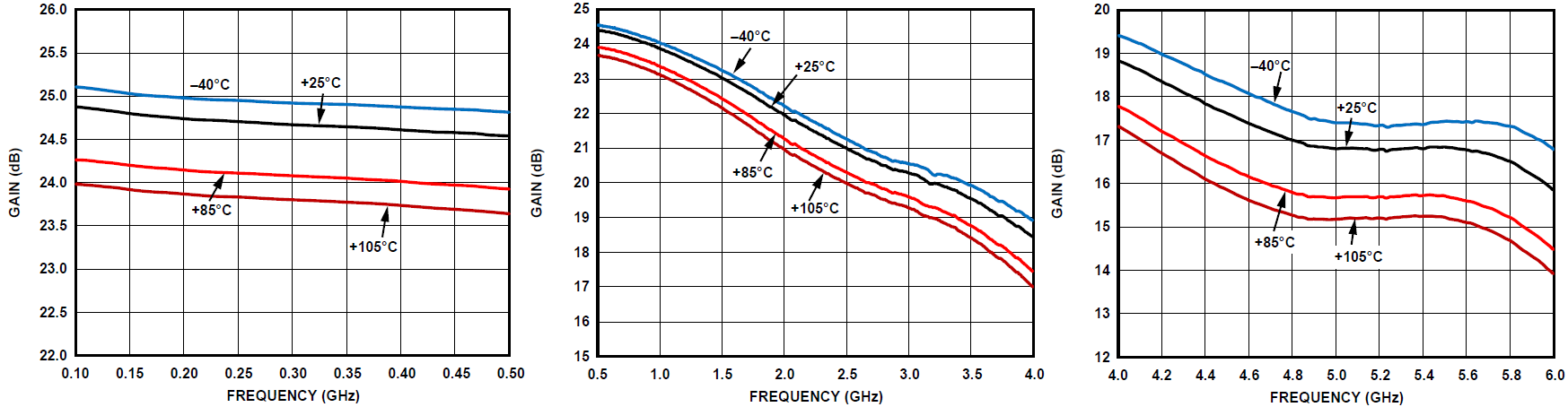
Figure 5: Gain vs. Frequency and Temperature (Click to enlarge)
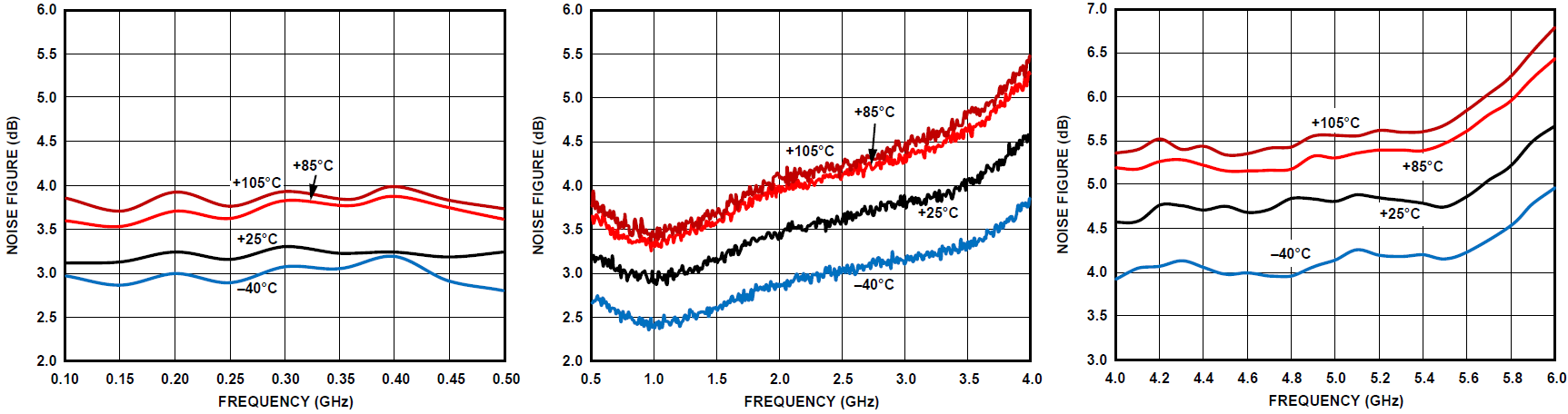
Figure 6: Noise Figure vs. Frequency and Temperature (Click to enlarge)
Part II: Testing
The preamplifier was tested by measuring the EMI of the 100Mhz Oscillator as Figure 7 and Figure 8. The Magnetic Field Probe was connected to the Channel 1 of the oscilloscope Rigol DS2202 with/without the preamplifier and the distance between the probe and the Oscillator was fixed.
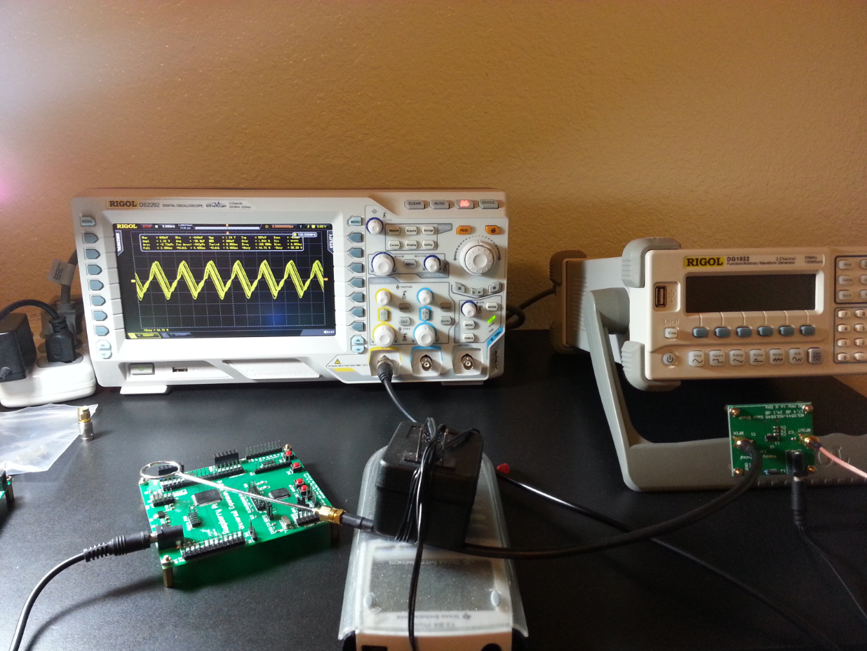
Figure 7: Equipemnts Setting Up
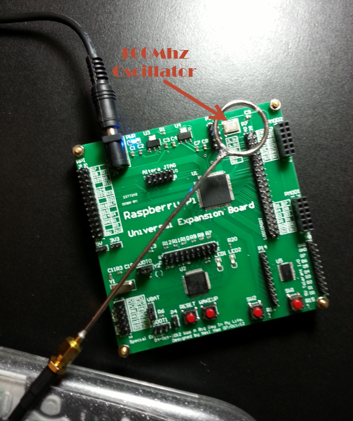
.Figure 8: Measuring the EMI of a 100Mhz Oscillator
When there was no preamplifier, the Vpp on the Channel 1 was 122mV.
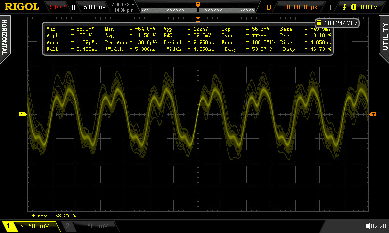
.Figure 9: The measurement when the probe connecting to the oscilloscope directly (without preamplifier)
When the preamplifier of ADL5544 edition used, the Vpp on the Channel 1 was 1.24V.

Figure 10: The measurement when using the preamplifier of ADL5544 edition
When the preamplifier of ADL5545 edition used, the Vpp on the Channel 1 was 3.40V.
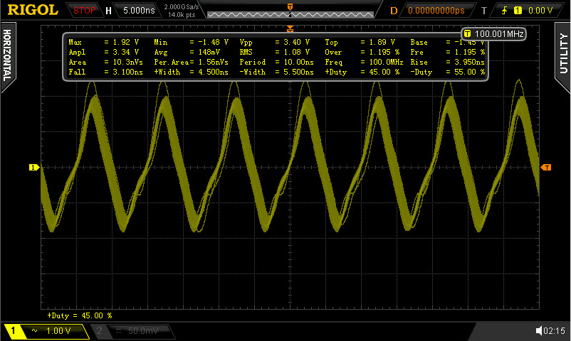
Figure 11: The measurement when using the preamplifier of ADL5545 edition
Part III: References
[1] ADL5544 Data Sheet. Retrieved August 18, 2013, from http://www.analog.com/static/imported-files/data_sheets/ADL5544.PDF (Local Mirror)
[2] ADL5545 Data Sheet. Retrieved August 18, 2013, from http://www.analog.com/static/imported-files/data_sheets/ADL5545.PDF (Local Mirror)
[3] Balun Design. Retrieved July 2, 2013, from http://www.odyseus.nildram.co.uk/RFMicrowave_Circuits_Files/Balun%20Design.pdf (Local Mirror)