Part I: Magnetic Field Probe
The theories behind the Magnetic Field Probe (Near Field Probe) is not very complex. Roy Ediss well stated the theories and the various designs of the Magnetic Field Probes in his article, Probing the Magnetic Field Probe. I implemented the design 2(a) which mentioned in the Roy Ediss's article. I used RG405 (Semi-rigid Coax Cable with Copper Outer Conductor) and a SMA connector [male body (inside threads) with male inner pin] in my implementation, it is shown in the Figure 1.
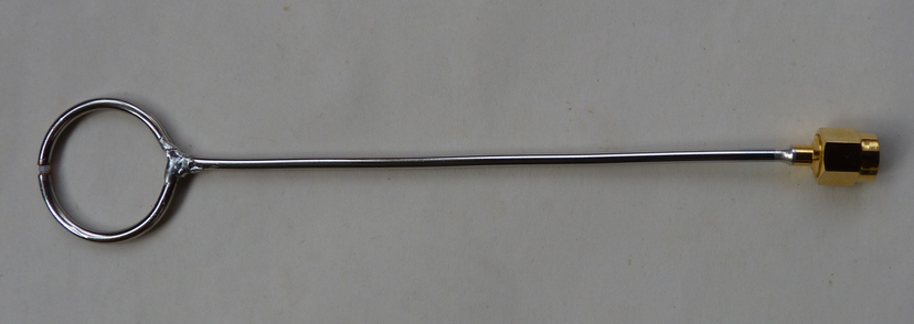 Figure 1:Magnetic Field Probe
Part II: Preamplifier
The gain of the oscilloscope may not enough to measure weak EMI signals. Therefore I designed a preamplifier which can amplify the EMI signals by the gain of 10. The circuit board is shown in the Figure 4.
A 1.5 GHz Fully Differential Amplifier LMH6552 is used to amplify the EMI signal which is captured by the Magnetic Field Probe, and than the amplified signal will be sent to the transformer T1. T1 will convert the differential signal to the single-ended signal. Finally, the single-ended amplified signal will be sent to the oscilloscope Rigol DS2202 via BNC connector P5.
The preamplifier in the Figure 2 requires +-5V dual supplies. The dual supplies design is shown in the Figure 3, it uses the Inverting Charge Pump MAX1697 to generate the -5V from the +5V single supply.
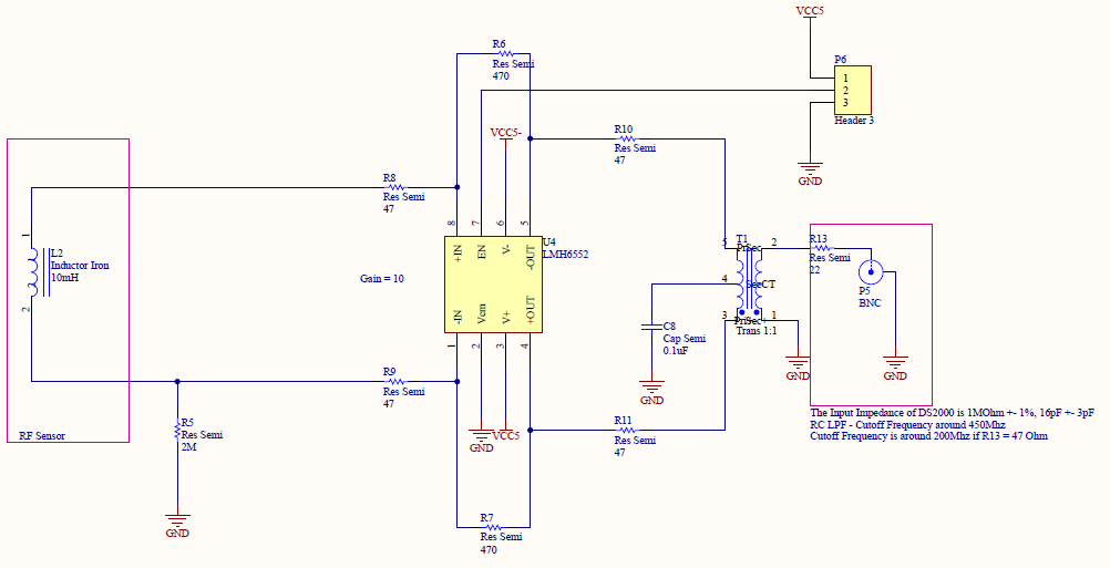
Figure 2: Schematic of the Preamplifier (Gain = 10)
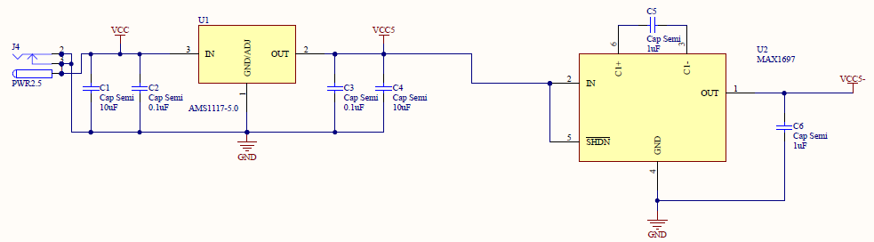
Figure 3: Schematic of the Voltage Regulator
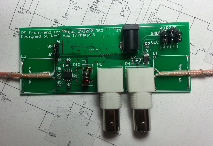
Figure 4: Preamplifier Board
Part III: Testing
1. Testing the Magnetic Field Probe with RF explorer (Spectrum Analyzer)
In this experiment, the Magnetic Field Probe was directly connected to the RF explorer's left SMA connector wich has 15-2700 Mhz bandwidth. The ring of the probe was put right above the 100 Mhz Oscillator as Figure 5. The measured frequency spectrum is shown in the Firgre 6. In the frequency spectrum, we can clearly see the 100Mhz Fundamental Frequency and its Harmonics.

.Figure 5: Measuring the EMI of a 100Mhz Oscillator
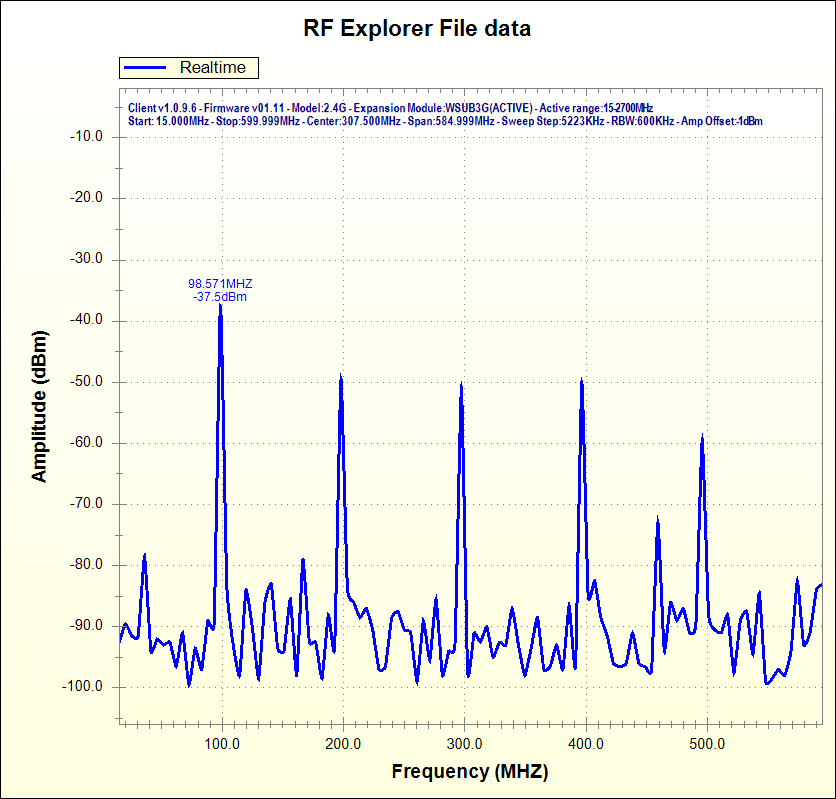
Figure 6: Frequency Spectrum showing the EMI of a 100Mhz Oscillator
2. Testing the Magnetic Field Probe with the oscilloscope Rigol DS2202
In the first part of this experiment, I connected the Magnetic Field Probe to the oscilloscope directly as Figure 7. The time domain and frequency domain results is shown in the Figure 8.
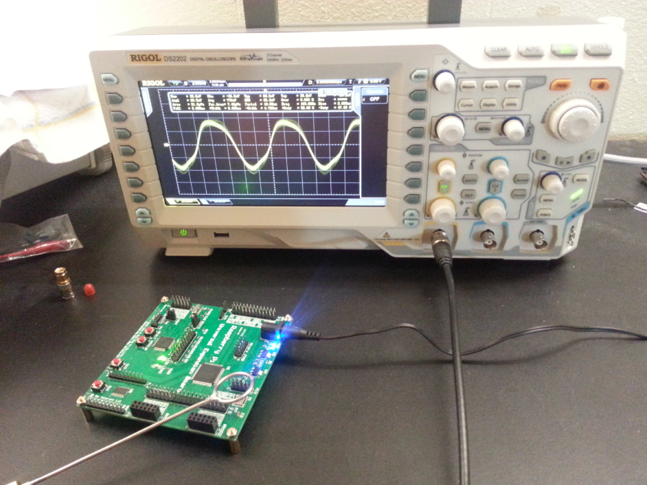
Figure 7: Measuring the EMI of a 100Mhz Oscillator (Without Preamplifier)
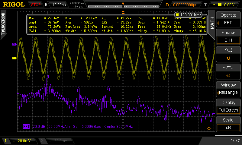
Figure 8: Time domain and Frequency domain results of the EMI (Without Preamplifier)
In the second part of this experiment, the EMI signal was amplified by the Preamplifier Board before sending to the oscilloscope, the connection is shown in the Figure 9. The time domain and frequency domain results is shown in the Figure 10. The time domain and the frequency domain results in the Figure 10 are similar to the results in the Figure 8, but the amplitude of the signal in the Figure 10 is 4.53 times of the signal in the Figure 8.
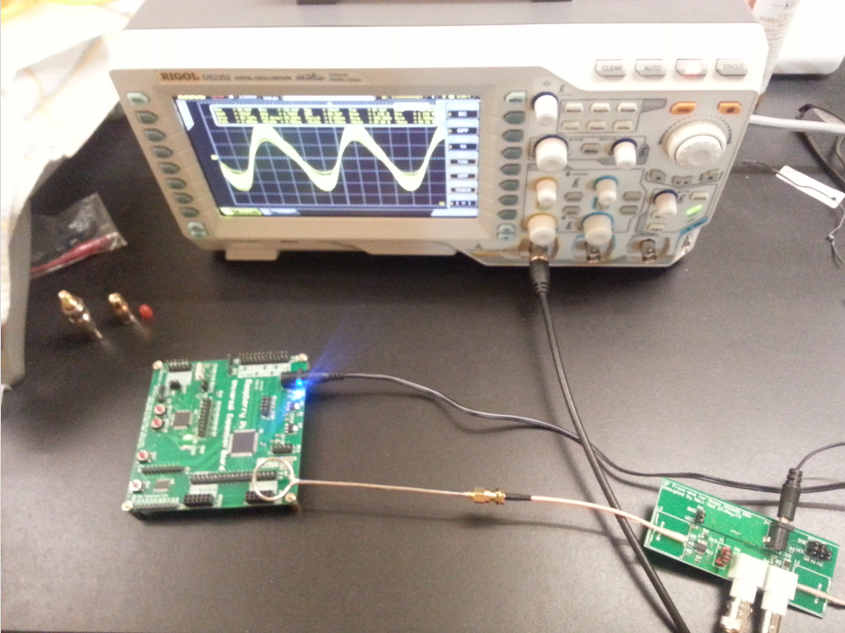
Figure 9: Measuring the EMI of a 100Mhz Oscillator (With Preamplifier)
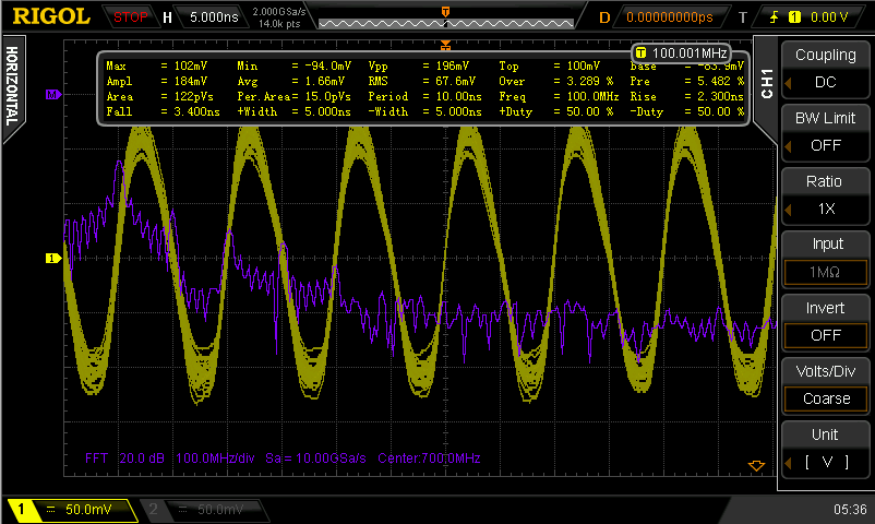
Figure 10: Time domain and Frequency domain results of the EMI (With Preamplifier)
Part IV: Datasheets
Part V: References
[1] Roy Ediss. Probing the Magnetic Field Probe. Retrieved from http://www.compliance-club.com/archive/old_archive/030718.htm (Local Mirror)